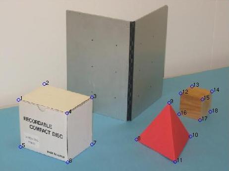

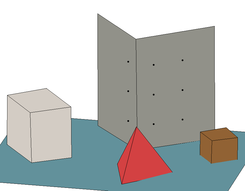
In this lab exercise you will use the calibration data calculated in Lab 7 on the images, stereo1.jpg and stereo2.jpg to reconstruct 3D information about the scene in these images.
Listing of stereo.m
% STEREO
%
% Usage: pt3D = stereo(im1, im2, C1, C2)
%
% Where:  im1 and im2 are the two stereo images
%         C1 and C2 are the calibration matrices
%         for these two images respectively
%
% The function will prompt you to digitise some points in the first image
% (finishing by clicking the right button).  The function then
% prompts you to digitise the equivalent points (which you must digitise
% in exactly the same sequence) in the second image.
% The function then solves the stereo equations
% and returns the 3D coordinates of the points in pt3D.
function pt3D = stereo(im1, im2, C1, C2)

    fprintf(1, 'Digitise some points in figure 1\n');
    figure(1)
    imshow(im1);
    [u1,v1] = digipts;
    fprintf(1, 'Digitise some points in figure 2\n');
    figure(2)
    imshow(im2);
    [u2,v2] = digipts;

    % check if same number of points are selected
    if length(u1) ~= length(u2)
        fprintf(1, 'Same number of points not selected\n');
    end

    for i = 1:length(u1)
        a = [C1(1:2,1:3) - [u1(i)*C1(3,1:3); v1(i)*C1(3,1:3)];
             C2(1:2,1:3) - [u2(i)*C2(3,1:3); v2(i)*C2(3,1:3)]];
        c = [u1(i) - C1(1,4);
             v1(i) - C1(2,4);
             u2(i) - C2(1,4);
             v2(i) - C2(2,4)];
        b(:, i) = a \ c;
    end
    pt3D = b';
pt3D = [-287.4992  158.1141  143.3739
        -173.9468  164.2097  143.1560
        -175.3143   14.7507  141.1366
        -290.1675   12.2712  143.6394
        -285.8033  160.3430    8.2383
        -286.8887   12.2176    6.3721
        -172.2206   15.0332    3.4689
         -86.0006  -70.0496    1.0623
         -68.9215 -147.1819  125.1224
          20.7269 -179.1217   -4.6303
        -137.1235 -207.1395   -0.1451
         134.8328  -92.2062   63.3233
         207.7907  -93.5088   61.5312
         209.3196 -159.1696   58.2119
         137.6326 -155.7202   58.6228
         135.9920  -92.8646   -6.4432
         136.2160 -159.7846   -9.3104
         206.6607 -163.1632  -10.7436]
I will first go through the code I used to obtain the lengths,
    % pt3D contains the coordinates of each unique vertex
    % a face matrix specifies how to connect these vertices to form sides.
    %
    % hence for a cube (following the given numbering), in general we have
    %     cubefaces = [4 1 2 3
    %                  4 3 7 6
    %                  4 6 5 1
    %                  8 5 1 2
    %                  8 2 3 7
    %                  8 7 6 5];
    % similarly for a tetrahedron, we have
    %     tetrahedronfaces = [1 2 3
    %                         1 2 4
    %                         1 3 4
    %                         2 3 4];
    %
    % hence we can make a function that determines the lengths of a face
    % by inputing the vertex and face matrix.

    function [slengths, nface] = sidelengths(pt3D, face)
        [rows, cols] = size(face);
        nface = [face face(:,1)];
        for i=1:cols
            for j=1:rows
                slengths(j,i) = norm(pt3D(nface(j,i),:)-pt3D(nface(j,i+1),:));
            end
        end
    end
The results obtained for the box, tetrahedron, and cube where as follows:
Length matrix of box face sides


slengths =

  145.8540  110.3015  144.8299  114.4853
  114.4853  134.3559  113.9037  135.9337
  135.9337  149.6496  133.8096  145.8540
  112.5680  133.8096  110.3015  135.9337
  135.9337  144.8299  134.3559  146.6334
  146.6334  113.9037  149.6496  112.5680


nface =

     4     1     2     3     4
     4     3     7     6     4
     4     6     5     1     4
     8     5     1     2     8
     8     2     3     7     8
     8     7     6     5     8


Length matrix of tetrahedro face sides


slengths =

  147.7079  160.2307  152.0356
  147.7079  154.4157  149.1688
  152.0356  158.6128  149.1688
  160.2307  158.6128  154.4157


nface =

     1     2     3     1
     1     2     4     1
     1     3     4     1
     2     3     4     2


Length matrix of cube face sides


slengths =

   66.8509   68.1830   61.4854   74.5177
   74.5177   67.2932   74.1407   68.4982
   68.4982   67.2958   67.7235   66.8509
   67.8666   67.7235   68.1830   68.4982
   68.4982   61.4854   67.2932   62.7262
   62.7262   74.1407   67.2958   67.8666


nface =

     4     1     2     3     4
     4     3     7     6     4
     4     6     5     1     4
     8     5     1     2     8
     8     2     3     7     8
     8     7     6     5     8
Hence for the cube, we convert the vertices to the standard, where the vertices are labeled the same as the box.
Then looking at the nface matrix the length between vertice 4 and 1 corresponds to a length of 66.8509, the length between vertice 1 and 2 corresponds to a length of 68.1830, and so on...
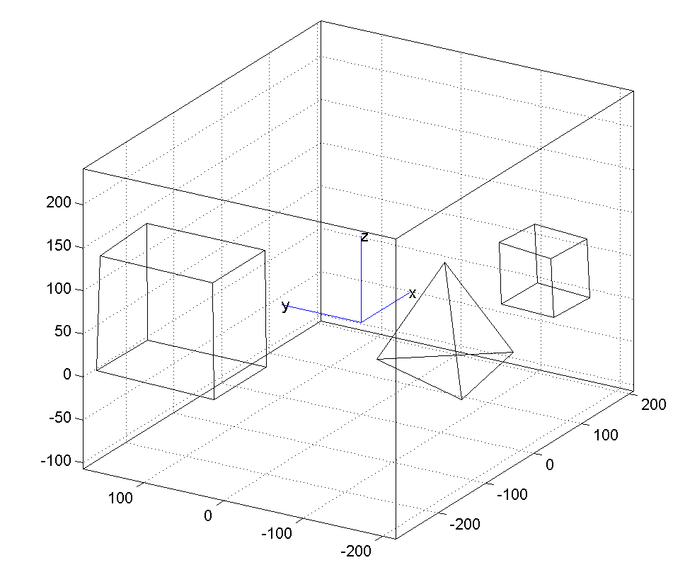
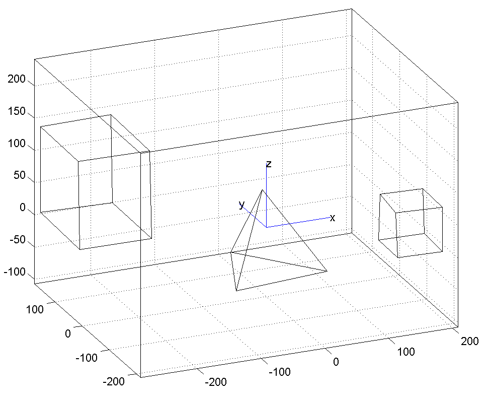
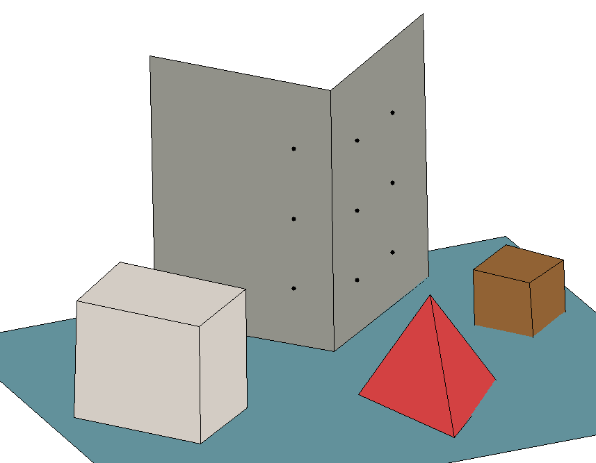
lab8.m used for wireframe images
lab8colour.m used for above images